Scan pattern
Blickfeld sensors are scanning LiDARs. Scanning LiDARs usually conduct subsequent measurements, each comprising only single or a couple of points in space in one direction at a time. In contrast to flash LiDARs, the whole field of view is, therefore, not covered at once but rather within a certain time frame. Blickfeld’s LiDAR sensors use two MEMS mirrors to deflect a collimated laser beam in the desired direction. The angle of both mirrors define the direction the system is looking at. A ‘time of flight’ measurement then determines the distance of the object to the LiDAR. Both mirrors oscillate at a given eigenfrequency and the relative phase of both mirrors defines the trajectory. The resulting laser beam trajectory for maximum amplitude of both scanners circumscribes the field of view (FoV).
Working principle of the Blickfeld Scanner
The Blickfeld LiDAR consists of two mirrors that oscillate with the same frequency. Both mirrors are identical and differ only in their orientation (one vertical, one horizontal) and in their relative phase and amplitude. Together, they create a Lissajous curve with a frequency ratio of \(1:1\) , a phase difference of \(\Delta \phi = 1/4 \pi\), and a variable amplitude ratio.
Horizontal mirror
The two mirrors, both with the natural frequency \(f\), create a scan pattern with the frame duration \(T\). Hereby, \(T\) is always an integer multiple of \(1/f\). The horizontal mirror oscillates in a continuous sinusoidal motion. One frame is comprised of one full oscillation period of the mirror. The resulting horizontal angle \(\theta_H\) can be described as follows:
\(\theta_H(t) = \theta_{H,max} / 2 \cdot \cos(2\pi f t)\)
With the horizontal field of view \(\theta_{H,max}\) (which can be chosen freely within the physical limitations of the horizontal mirror).
The blue line in Figure 1 below shows a plot of the horizontal angle \(\theta_H\) for an exemplary frame with an eigenfrequency of \(f=150 Hz\), a horizontal Field of View \(\theta_{H,max}=80\deg\), 40 scanlines (20 periods) and a duration of \(T=2 \cdot 1/f\).
Vertical mirror
The vertical mirror has a phase offset of \(\Delta \phi = \pi / 4\) with respect to the horizontal mirror and a variable amplitude that is described by the ramp function \(r(t)\). The vertical angle can therefore be written as:
\(\theta_V(t) = r(t) \cdot \theta_{V,max} / 2 \cdot \sin(2 \pi f t)\)
The vertical field of view \(\theta_{V,max}\) can also be chosen freely within the physical limitations of the vertical mirror.
Ramp function
The ramp function consists of two segments. During the first half of the frame it is a strictly monotonically increasing function from 0 to 1, while during the second half, it is a strictly monotonically decreasing function from 1 to 0. An exemplary function consisting of two linear areas can be described as:
\(r(t) = 4/3 t / T\) for \(t \in [ 0; 3/4 T ]\)
\(r(t) = 4 - 4t / T\) for \(t \in ] 3/4 T; T ]\)
Note that these linear functions are only exemplary. To create different densities of scan lines, throughout the scan pattern, ramp functions with varying slopes, or nonlinear ramp functions can be chosen (the maximum slope of these functions is limited by the characteristics of the mirror). The spacing of the scan lines can therefore be controlled by adjusting the ramp function \(r(t)\).
The ramping phases are known as the up-ramping phase and the down-ramping phase.
The orange line in the following figure 1 shows a plot of the vertical angle \(\theta_V\) for an exemplary frame with a natural frequency \(f=150 Hz\), a vertical field of view \(\theta_{V,max}=30\deg\), and the ramp function \(r(t)\) defined in the previous example.
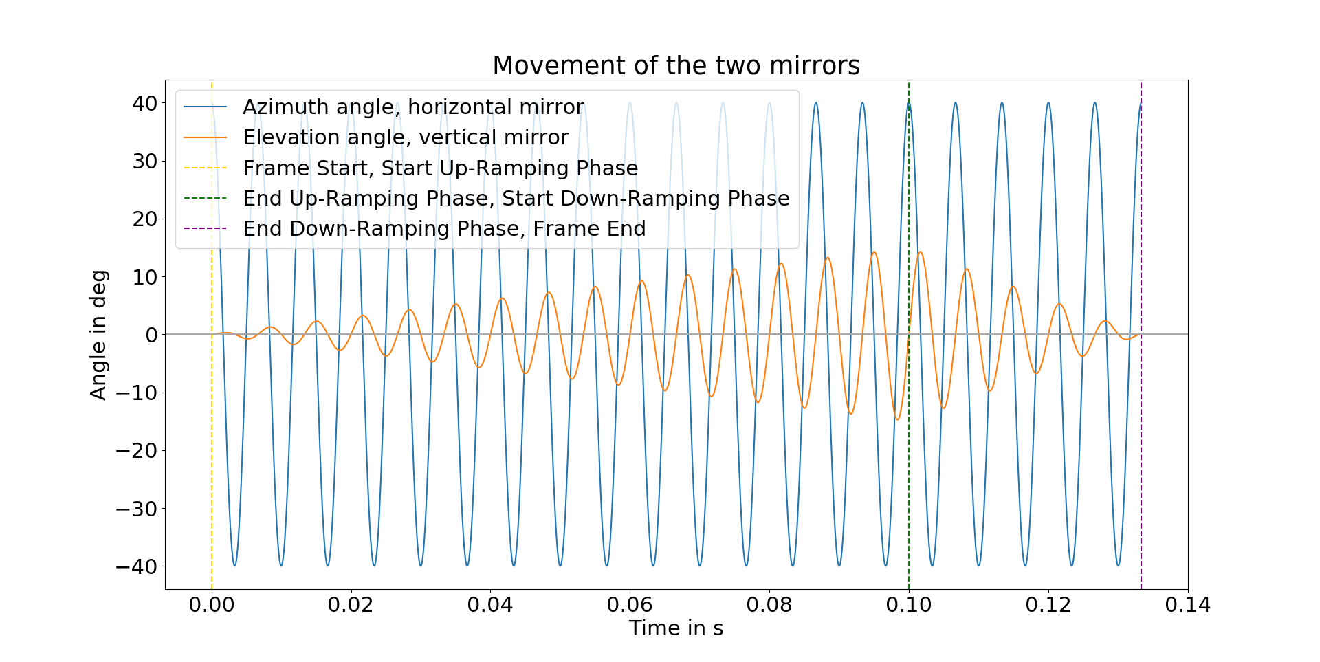
Figure 1: Movement of the horizontal mirror (blue) and the vertical mirror (orange).
Scan lines
One scan line is defined as half of the period of the horizontal mirror’s oscillation, i.e. a movement of the laser beam from right to left or from left to right.
The number of scanlines per frame \(N\) results from the following equation:
\(N = 2 T f\)
By altering the number of scan lines per frame, you can directly decrease or increase the frame duration \(T\). As the frame rate of the system is equal to \(1/T\), the frame rate is inversely proportional to the number of scan lines per frame.
The horizontal mirror starts on the left and moves to the right. The vertical mirror starts at zero and moves to the bottom. As depicted in figure 2, the first scan line is nearly a straight line in the middle from left to right. The second scan line is above the first scan line and moves from right to left. The third scan line is below the first scan line and moves from left to right. The fourth scan line is above the second scan line and moves from right to left, and so on.
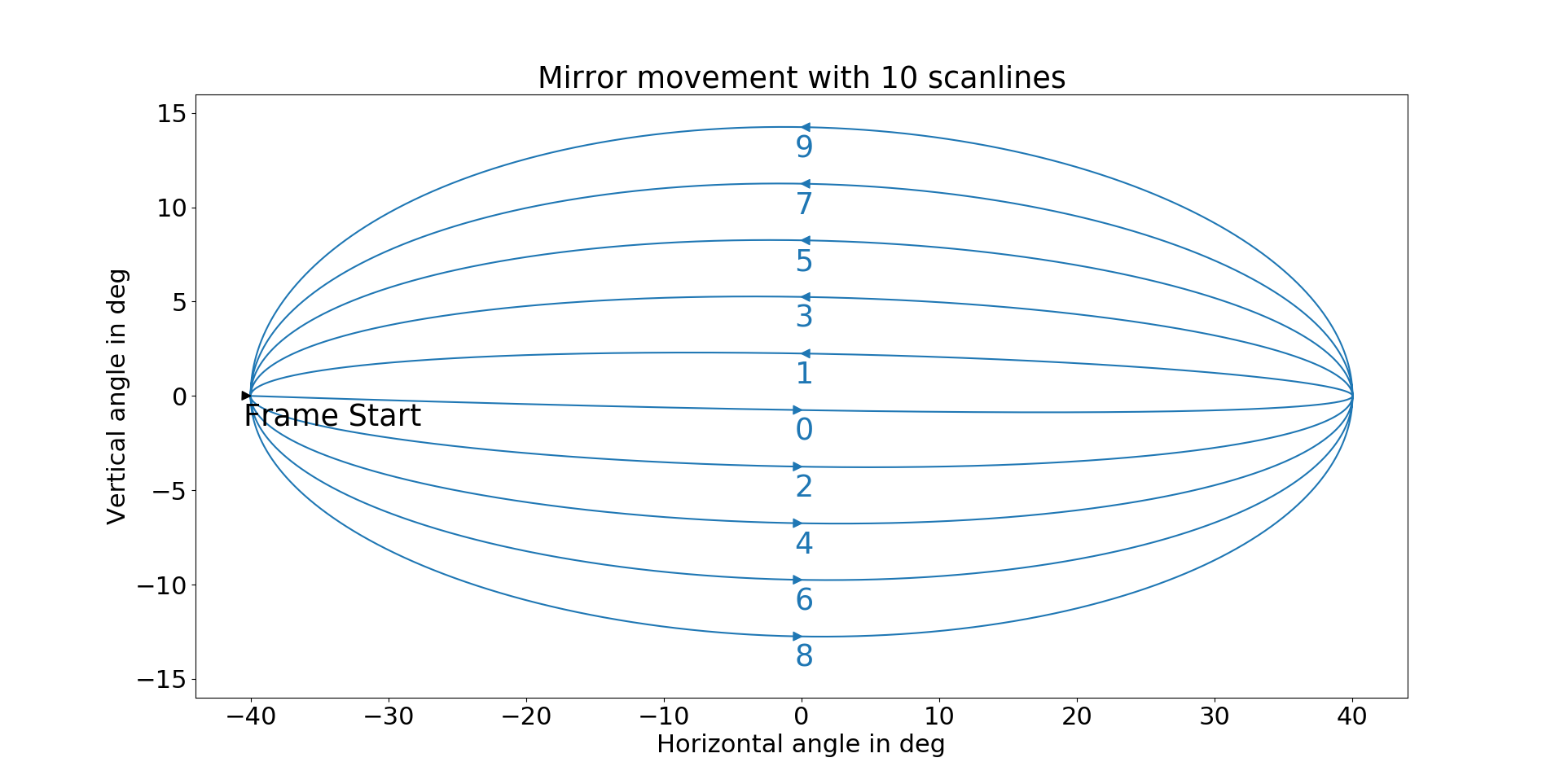
Figure 2: Movement of the laser beam, if the laser diode were continuously emitting.

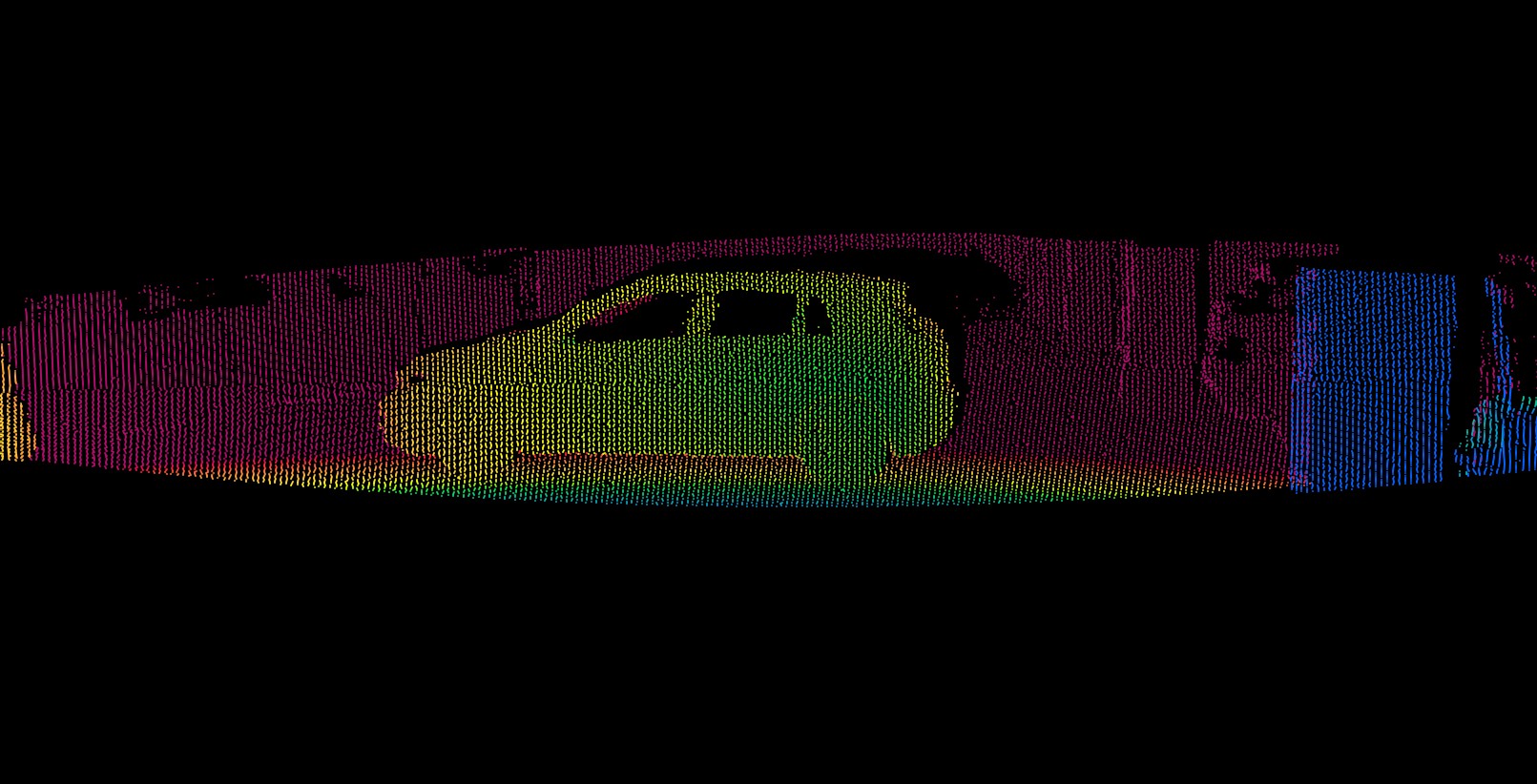
Figure 3: Scan of a car with different line densities.
Configuring the scan pattern
The WebGUI can be used to configure the scan pattern manually. If you want to change it programatically, use the Blickfeld Scanner Library.
The following parameters can be defined (see also protobuf definition: Scan Pattern)
The number of scan lines for the up-ramping phase and the down-ramping phase.
Optical vertical and horizontal FoV.
Laser pulsing mode in the up-ramping phase, the down-ramping phase, or both.