Sensor setup
In Percept, you can opt for either a single LiDAR or a multi-LiDAR setup. This section aims to help you decide which setup suits your needs.
The choice of the number of LiDAR devices to deply heavily depends on the specific use case and the environment in which these devices will be installed. The following subsections provide information to assist in determining whether a single LiDAR is sufficient or if a multi-LiDAR setup is necessary.
In order to ease the alignment process, reference objects in the scene can be used to align the sensors according to a provided layout plan. Hence, the orientation of the individual sensors can be aligned in a way that reference objects (i.e. box, ton, person, etc.) can be detected. Figure 1 shows the general idea behind this method.
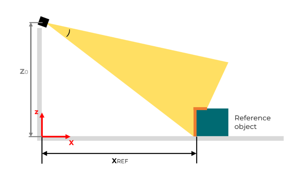
Based on measurements, the position of a reference object XRef can be calculated. After a reference object has been placed in the scene at the given coordinates, the sensor’s pitch angle can be adjusted until the sensor-facing part of the reference object is fully visible. Then the correct pitch angle is set.
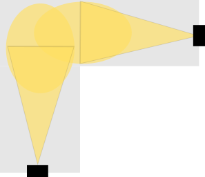
Single LiDAR setup
The basic setup involves a single LiDAR, which is capable of facilitating various projects.
This setup offers the advantage of a straightforward installation. Mounting just one LiDAR and adjusting its orientation to cover the desired area is all that’s required.
This setup is particularly beneficial:
-
When the area to be covered fits within the field of view of one device.
-
When there are no blind spots in the area of interest.
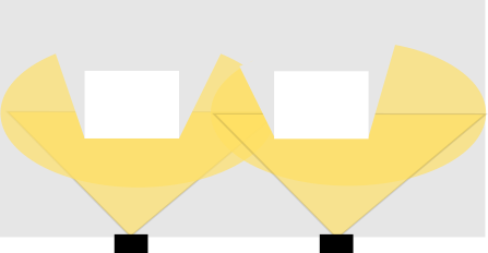
Multi LiDAR setup
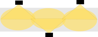
In a multi-LiDAR setup, we assume the presence of at least two LiDARs positioned to create an overlapping area.
A multi-LiDAR setup becomes necessary when dealing with:
-
Areas too large or convoluted to be covered by a single LiDAR.
-
Challenging mounting positions, such as limited mounting heights.
-
Significant occlusions, like pillars or walls.
-
A combination of the above factors.
| To register point clouds accurately, there must be an overlap between them. |
Coverage of large or convoluted areas
The need for a second LiDAR may arise when a single device cannot cover an area adequately. Additionally, corners in the monitored area might necessitate an additional sensor to provide a wider view.
Adding an extra sensor may be necessary due to increased point spacing with distance from the device. This disparity can result in fewer points returned by an object or even its disappearance between scan lines or points. Consequently, detecting smaller objects reliably becomes more challenging. Mounting an additional LiDAR, perhaps from the opposite direction, can enhance the overall detection performance.
Difficult mounting positions
Optimal mounting positions are crucial for effective area coverage. Sensors mounted too high may cover a larger area but could lose information due to increased point spacing in the distance. Conversely, sensors mounted too low might miss objects in close proximity due to minimum range requirements or obstruction by objects in front.

Occlusion
Various types of occlusion may occur, including moving objects blocking the view or static obstacles like walls and pillars creating blind spots. Mounting an additional sensor from a different angle can help mitigate these blind spots.
In order to avoid blind spots or occlusions after registration of combined point clouds, it is recommended to do the registration step when a scene is still empty. In this case, sensor positions and orientations can still be corrected.
Point cloud allignment
Once all sensors have been mounted, the final sensor alignment can be conducted. The main goal of this step is to have the sensors precisely aligned according to the provided plan/simulation results.
The alignment step aims to align the point cloud’s ground area on the virtual grid of the XY plane. This alignment is crucial for effective zone management, comprehension of the 3D scene, and it’s a prerequisite for optimal performance of security and volume monitoring applications.
The alignment transformation is automatically computed for each LiDAR device to position the point cloud onto the virtual grid. This process involves shifting the point cloud onto the grid and orienting it to align the detected ground with the grid. This automatic method utilizes the IMU sensor within the device along with an algorithm designed to identify the ground plane. Reviewing the outcome of the auto-alignment is advised, allowing for adjustments to the LiDAR’s position and orientation if necessary.
An empty scene, characterized by homogeneous geometry, may pose challenges during the registration step as it may complicate the identification of overlapping areas between distinct point clouds. To simplify this process, it is advantageous to position reference objects within the empty scene, preferably in overlap zones, which can be detected by multiple sensors. These objects serve as reference points for seamlessly stitching the point clouds together.
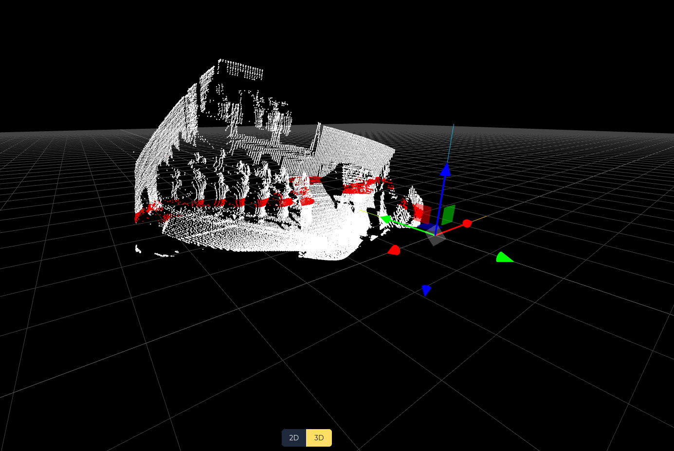
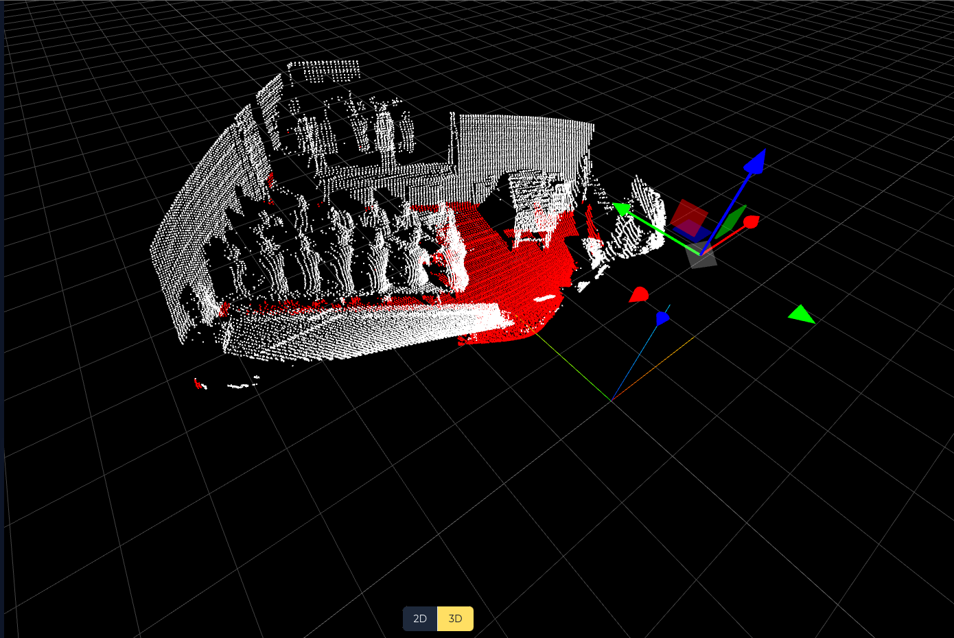
Point cloud registration
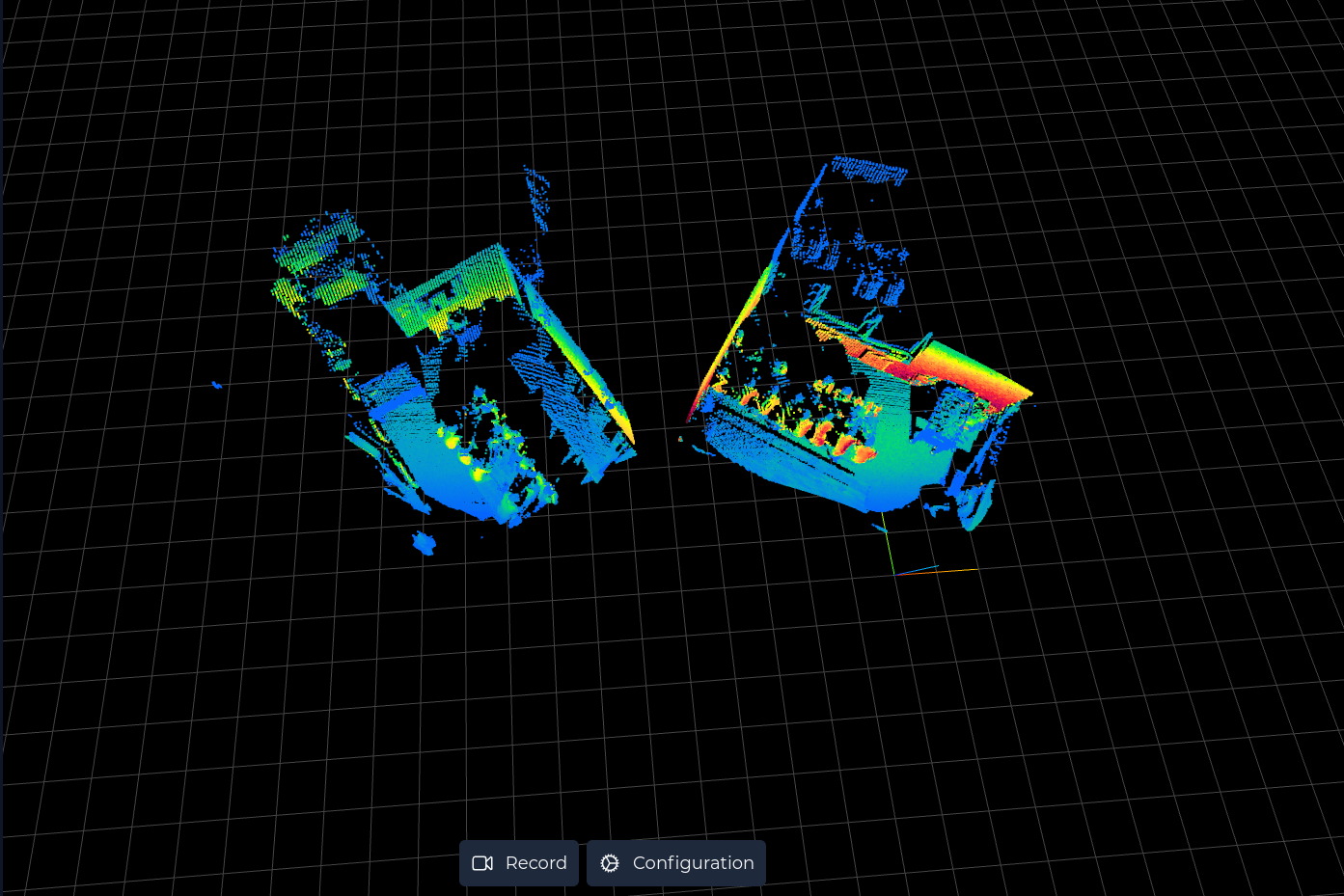
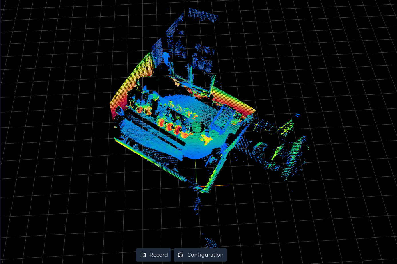
When using multiple LiDAR devices in your setup, registration becomes essential for sensor fusion. This process involves combining distinct point clouds from various devices into an unified single point cloud. This is achieved by determining the relative position and orientation of the devices concerning each other. This registration step is crucial for merging diverse sensor measurements, enabling the utilization of their data as if it originated from a single sensor with a broader field of view or greater point cloud density.
The sensor setup enables users to align each point cloud to approximate matching positions. Utilizing auto-alignment facilitates this process seamlessly. Subsequently, Percept fine-tunes the transformation for precise registration. If necessary, users have the option to bypass refinement and directly apply manual transformations. In this scenario, point clouds retain their manually set positions without undergoing refinement.
|
It is recommended to refine transformations for registering point clouds. Avoiding the refinement step is advisable only if the refinement doesn’t enhance registration or when registration isn’t necessary (e.g., when multiple LiDAR devices lack overlap). |
|
Assess the refinement outcome before proceeding. If the result isn’t satisfactory, users have the chance to retry and make additional adjustments. |