Mirasys
This section provides information on how to integrate QbProtect with Mirasys VMS. Please refer to the ONVIF section beforehand for general information on using ONVIF with QbProtect.
|
The following Mirasys components have been used in the examples below:
|
Add Device
|
Events originating from dynamic event sources (e.g. security zones) have to be correctly exposed to the VMS each time a new zone configuration is introduced via WebGUI.
Please either pre-configure all the required security zones in WebGUI before adding the QbProtect into the VMS or re-initialize the existing QbProtect in the Mirasys System Manager ( |
The Mirasys System Manager is used to add QbProtect into Mirasys VMS. The procedure includes the following steps:
-
Launch the Mirasys System Manager and connect to the active recording server instance
-
Navigate to
VMS Serverstab → Double clickHardwareunder theLocal Recordertab → ClickAdd Deviceicon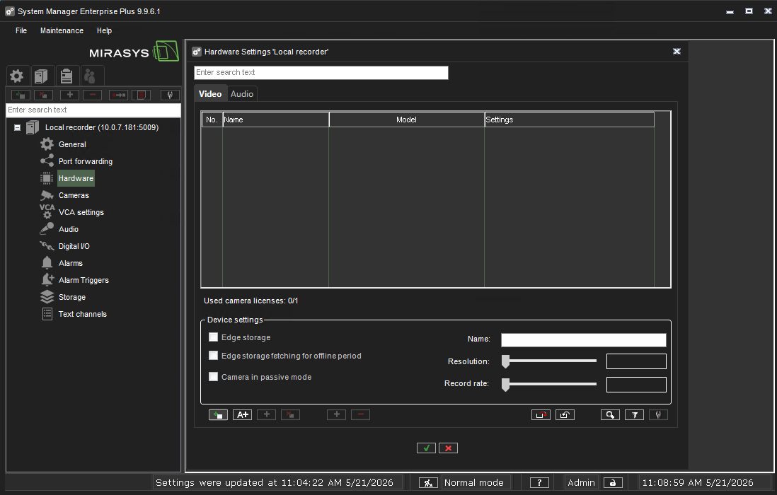 Figure 1. Adding QbProtect into Mirasys VMS: Add Hardware
 -
Set
DrivertoOnvifIPCapture→ Enter the FQDN or IP of QbProtect in theAddressfield → Set Port to443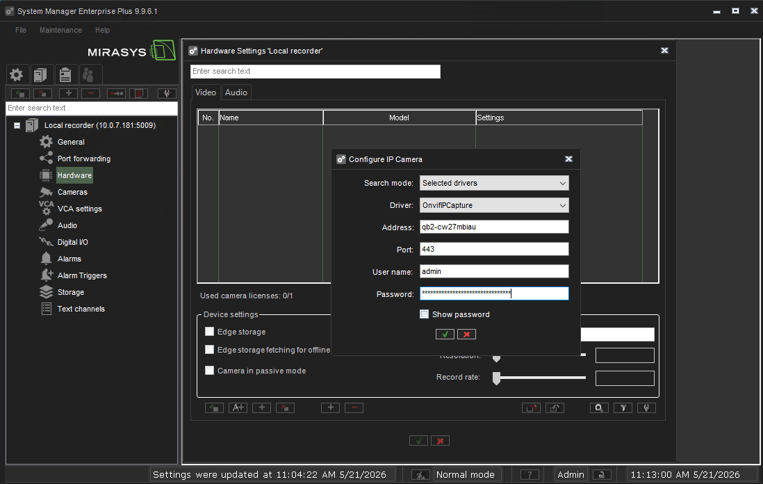 Figure 2. Adding QbProtect into Mirasys VMS: Configure IP Camera
 -
Set
Username name/Passwordin the corresponding credential fields → ClickOKPlease refer to the User authentication subsection to find out how to obtain valid ONVIF credentials required for QbProtect VMS integrations.
-
Accept IP camera driver → Click
OK→ The QbProtect will be detected as camera → Give a distinguishable name to the QbProtect device, e.g.QbProtect→ ClickOK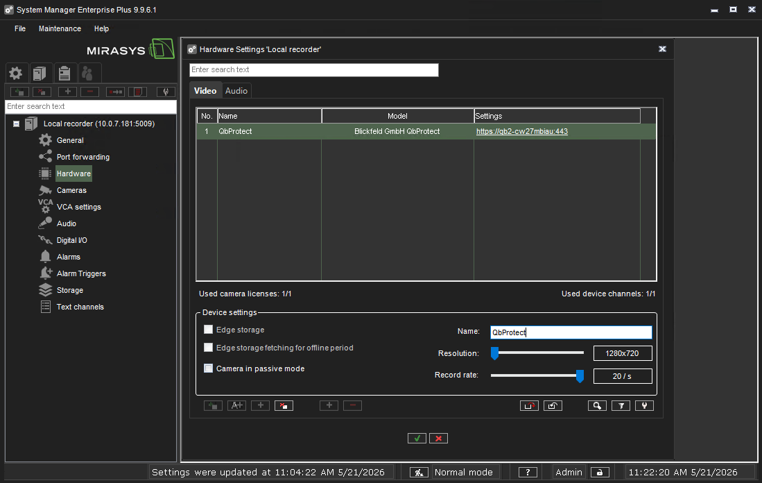 Figure 3. Adding QbProtect into Mirasys VMS: accept detected QbProtect
 -
Navigate to
VMS Serverstab → Double clickCamerasunder theLocal Recordertab → QbProtect should be visible under theGeneraltab → Make sure thatTransportTypeis set toRTP over HTTP→ The live RTSP preview of the point cloud should be available in theReference imagepreview window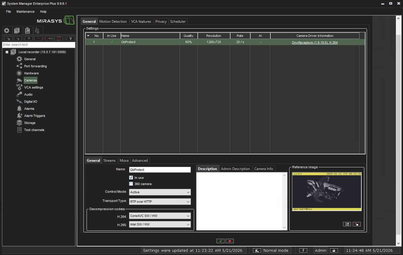 Figure 4. Adding QbProtect into Mirasys VMS: QbProtect transport type settings
 -
Launch the Mirasys Spotter and connect to the active recording server instance
-
QbProtect should be available under
Camerastoggle → Drag and drop it into the Mirasys Spotter viewer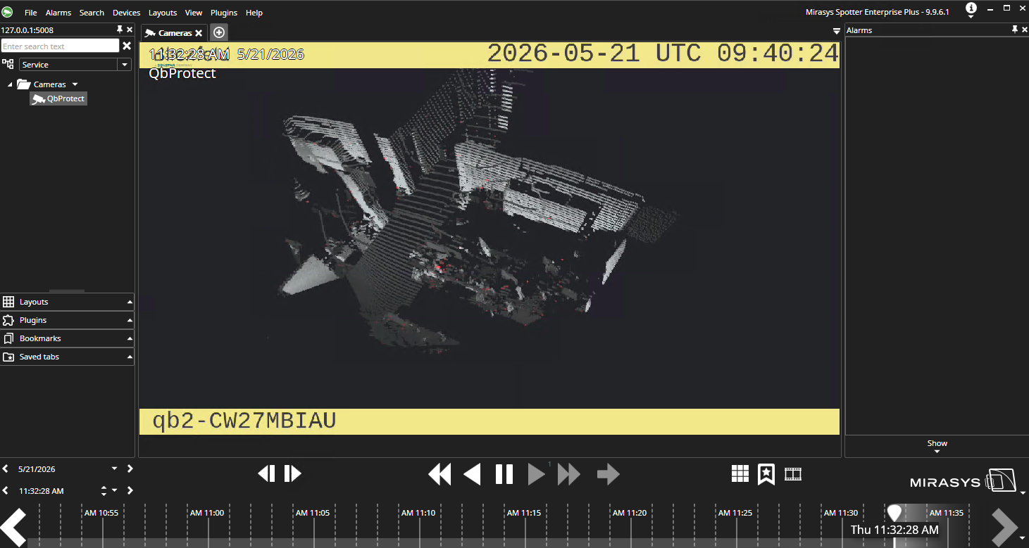 Figure 5. Adding QbProtect into Mirasys VMS: live video stream in Mirasys Spotter
|
The perspective of the RTSP video stream in VMS can be synchronized with the one configured in the WebGUI. For that, navigate to the Viewer page of the QbProtect WebGUI, configure the desired view perspective, and apply the keyboard shortcut Shift+V. |
The live video stream of the QbProtect point cloud can be accessed and observed in Mirasys Spotter viewer after successfully completing the required steps above.
Events
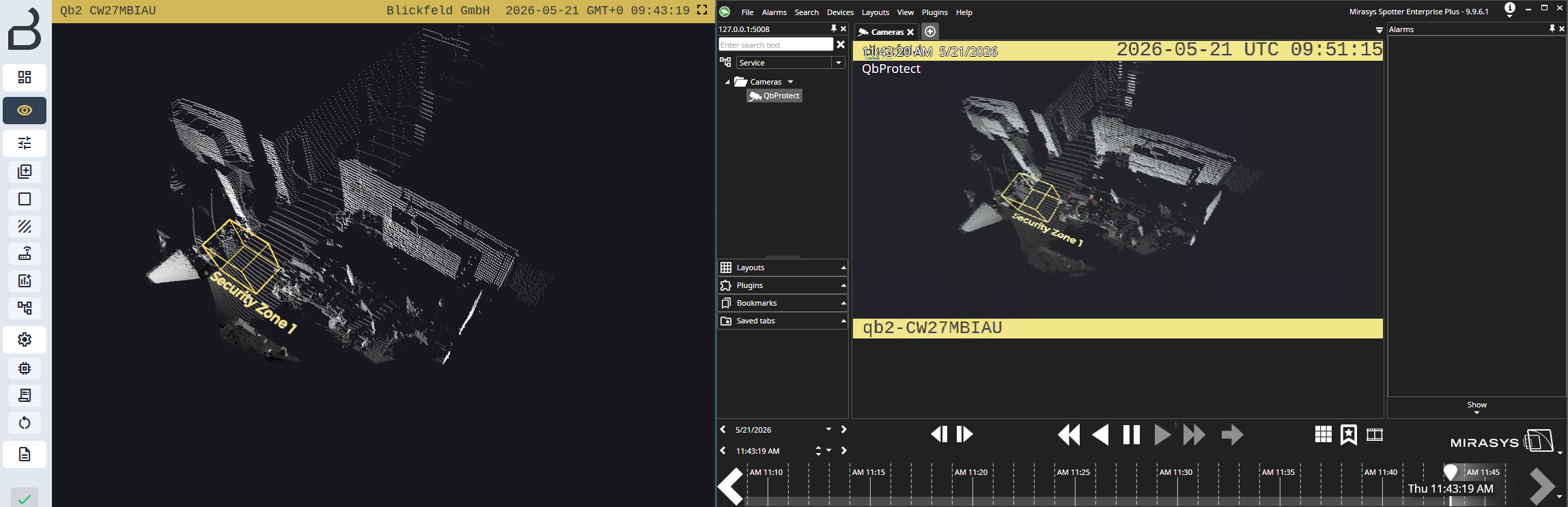
The example below shows how QbProtect events can be used to trigger alarms in Mirasys VMS. After QbProtect has been added to the Mirasys VMS, it can be configured to use QbProtect events for alarm generation. In this example, one security zone Security Zone 1 has been configured using QbProtect WebGUI to exemplify the configuration process, as shown in the Figure below.
|
Please refer to the Events subsection to learn about the available ONVIF event topics. |
Configure Events Handling
The events configuration procedure includes the following steps:
-
Launch the Mirasys System Manager and connect to the active recording server instance (optional)
-
Navigate to
VMS Serverstab → Double clickAlarm Triggersunder theLocal Recordertab → ClickAdd new alarm triggericon -
Set alarm type to
ONVIF→ The list of supported events should be shown in the topic drop-down list → SelectIntrusionZoneSecurityZone1topic from the list → Give a distinguishable name to the trigger source, e.g.Security Zone 1→ Click on thePlusicon for the additional filters configuration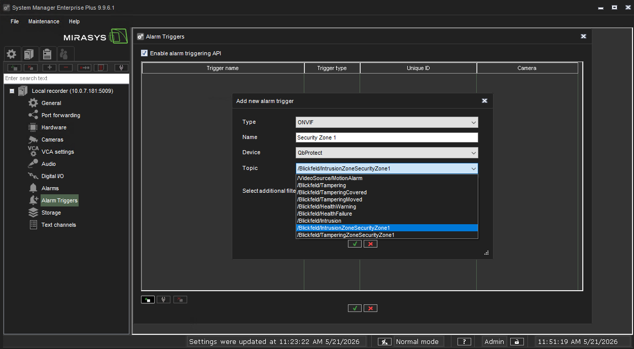 Figure 7. Mirasys System Manager alarm trigger configuration: create alarm trigger
 -
Click
Add Parameter→ Set Parameter name toState→ Set Value toTrue→ Set Operation toEqual→ ClickOK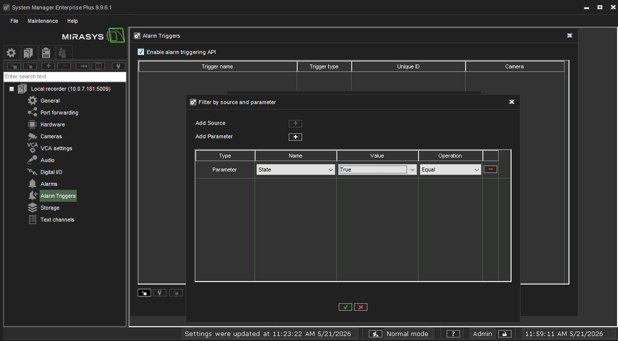 Figure 8. Mirasys System Manager alarm trigger configuration: configure alarm trigger filter
 -
The configured alarm trigger
Security Zone 1should be available in the list of the configured alarm triggers → Make sure thatEnable alarm triggering APIis active → ClickOKto finalize the trigger configuration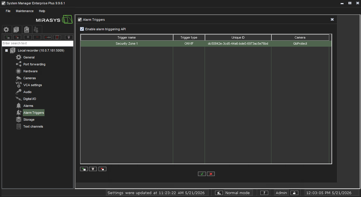 Figure 9. Mirasys System Manager alarm trigger configuration: alarm trigger for the Security Zone 1
Configure Alarm Rule Chain
The Mirasys VMS alarm rule chain maps the configured alarm trigger to a dedicated action (e.g. a particular alarm, recording of the video stream, etc.). The alarm rule chain configuration procedure includes the following steps:
-
Navigate to
VMS Serverstab → Double clickAlarmsunder theLocal Recordertab → ClickNew Alarmicon -
Navigate to the
Generaltab → Give a distinguishable name to the alarm configuration, e.g.Security Zone 1 - Intrusion Alarm→ Set priority toHigh→ Toggle alarmVisiblein Service profile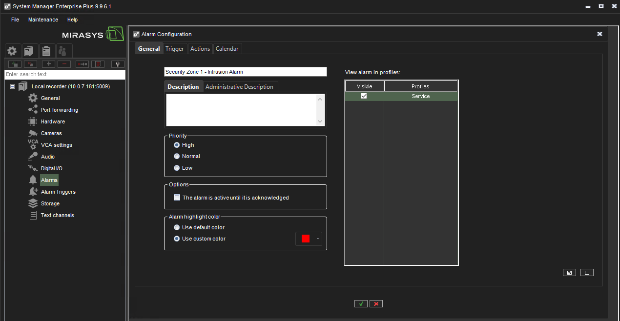 Figure 10. Mirasys System Manager alarm configuration: create alarm rule chain
 -
Navigate to the
Triggertab → Set type toMetadata→ Make sure thatSecurity Zone 1is in the Zone pane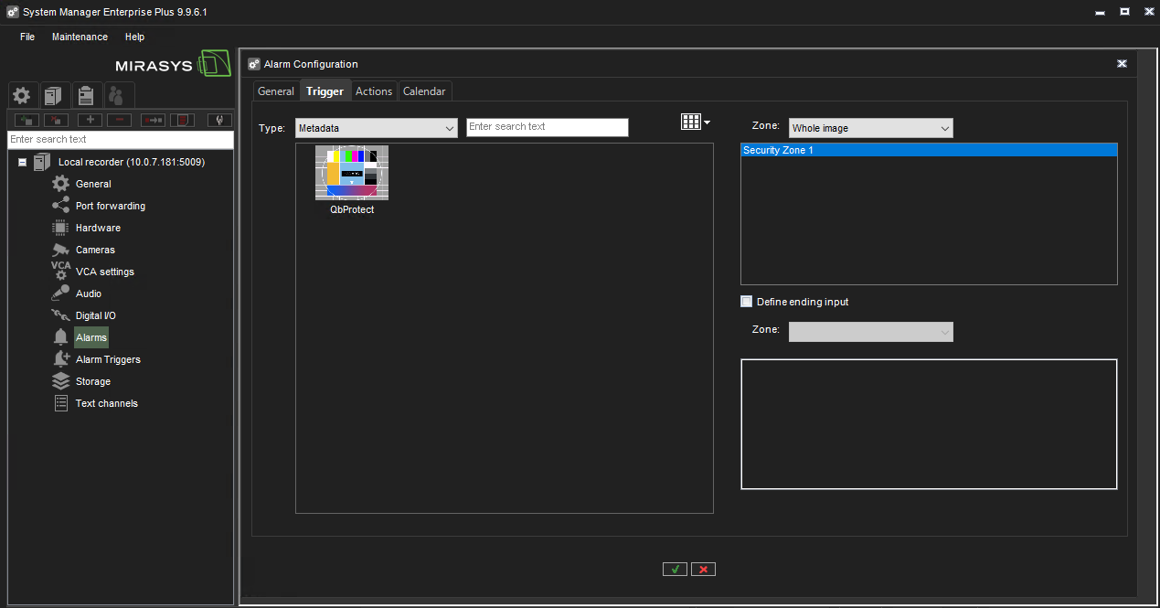 Figure 11. Mirasys System Manager alarm configuration: alarm rule chain trigger
 -
Navigate to the
Actionstab → SelectQbProtectin theTypepane → Select the desired action type, e.g.Disable alarms→ Click theRight Arrowicon to bring it to theVisiblepane → Set the highest filtered alarm priority toLow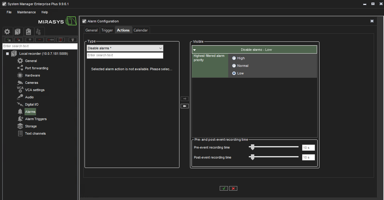 Figure 12. Mirasys System Manager alarm configuration: alarm rule chain action
 -
Click
OKto finalize the alarm rule chain configuration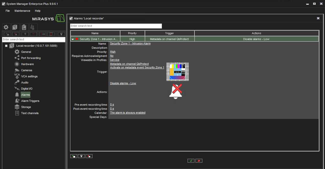 Figure 13. Mirasys System Manager alarm configuration: configured alarm rule chain
 -
The zone intrusion event in the Security Zone 1 from QbProtect and the configured intrusion event rule chain will be generating an alarm in Mirasys VMS Spotter, as shown in the Figure below.
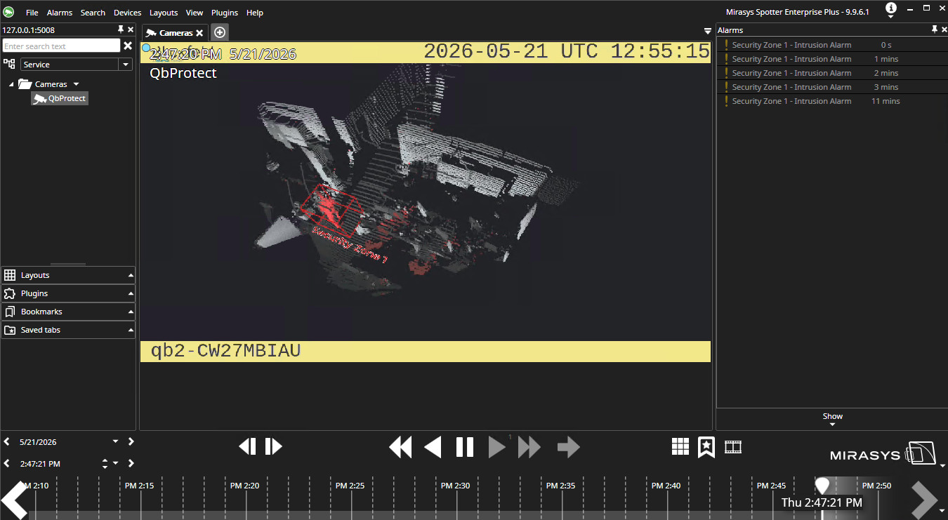 Figure 14. Mirasys Spotter: ONVIF intrusion event in the security zone raises an alarm